
3D for Print: Design Rules to Prevent Warping and Failures
A model can look perfect on screen and still fail on the printer. Warped corners, cracked walls, lifted bases, sagging overhangs, and parts that no longer fit together are usually symptoms of one core problem: the design was not prepared for the physics of printing.
If you are preparing 3D for print rather than for rendering, the goal is not just to make the part look right. The goal is to make it buildable, stable, strong enough for its use, and realistic for the material and process. Good printer settings matter, but smart design choices prevent many failures before the file ever reaches the slicer.
This guide focuses on practical design rules that reduce warping and print failures for custom 3D printing, especially when you want cleaner first attempts, better dimensional accuracy, and less wasted material.
Why warping starts in the design
Warping happens when different areas of a print shrink, cool, cure, or release stress at different rates. In FDM printing, hot plastic is deposited layer by layer, then contracts as it cools. If the bottom layers grip the bed while upper layers pull inward, corners can lift. In resin printing, curing forces, suction, hollow cavities, and unsupported surfaces can deform or crack a part.
A printer can compensate with bed temperature, enclosure control, support strategy, build plate adhesion, and slicer settings. Still, certain shapes are simply more failure-prone. Long flat plates, sharp rectangular corners, thick solid blocks, and tall narrow features are common culprits.
Designing for printing means asking a few questions early:
- Will this shape shrink evenly?
- Does the first layer have enough stable contact?
- Are thick and thin areas balanced?
- Can supports be removed without damaging important surfaces?
- Will the part still fit after material shrinkage, cleanup, or post-processing?
The earlier you answer those questions, the fewer failed prints you will have to troubleshoot later.
Rule 1: Choose the material before finalizing the geometry
Material is not a finishing detail. It affects shrinkage, flexibility, heat resistance, surface detail, and the likelihood of warping. A model designed for PLA may not behave the same way in ABS, ASA, nylon, or resin.
For example, PLA is generally easier to print because it shrinks less than many engineering thermoplastics. ABS and ASA can be excellent for tougher or more heat-resistant parts, but they demand more attention to geometry, enclosure conditions, and stress relief. Resin can capture fine detail, but hollow parts need drainage and venting to avoid suction and trapped resin.
| Material family | Typical warping risk | Good fit for | Design notes |
|---|---|---|---|
| PLA | Low | Display pieces, prototypes, light-duty parts | Avoid thin brittle snap features and hot environments |
| PETG | Low to moderate | Functional indoor parts, brackets, clips | Use generous clearances because PETG can be slightly stringy or flexible |
| ABS or ASA | Higher | Heat-resistant parts, outdoor parts, tougher housings | Round corners, avoid large flat slabs, consider splitting big parts |
| TPU | Low for warping, higher for flex-related issues | Flexible bumpers, feet, grips, gaskets | Add thickness where stiffness matters and avoid tiny unsupported details |
| Nylon and filled nylons | Moderate to high | Tough functional parts, wear-resistant components | Keep material dry, use ribs instead of huge solid masses, allow more tolerance |
| Resin | Geometry-dependent | Miniatures, high-detail models, smooth presentation parts | Add drainage, avoid suction cups, support delicate islands properly |
If you are not sure which material fits your part, define the part's job first. A decorative desk model, a replacement knob, a heat-exposed bracket, and a flexible cable strain relief should not all use the same design rules.
Choosing the correct material also supports more sustainable production. A print that succeeds on the first or second attempt wastes less filament, resin, electricity, packaging, and labor than a part that needs repeated trial and error.
Rule 2: Avoid large, sharp-cornered first layers
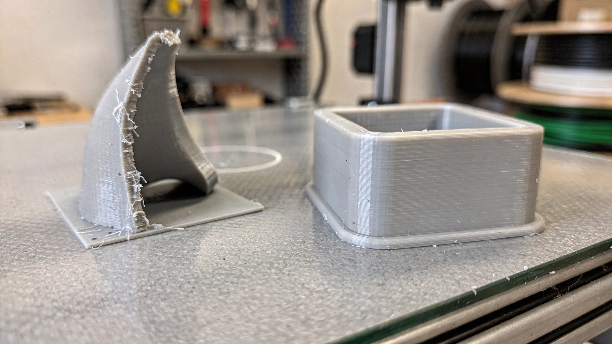
The first layer is where many failures begin. Large flat bases with sharp corners create stress concentration points. As upper layers cool and contract, the corners are pulled inward and upward. Once a corner lifts, the nozzle may hit the raised area, surface quality suffers, and dimensional accuracy is compromised.
A better design spreads stress more evenly. Rounded corners, chamfered edges, segmented footprints, and small adhesion helper features can make a dramatic difference.
For rectangular parts, even a modest corner radius helps. For large flat covers, trays, signs, panels, or bases, consider adding shallow ribs, slight curvature, or splitting the model into smaller sections. If the bottom surface does not need to be perfectly flat, a chamfer on the lower edge can also reduce the amount of plastic trying to contract at the outermost corner.
| Risky base feature | Common failure | Better design choice |
|---|---|---|
| Long rectangular base with sharp corners | Corners lift from the bed | Add rounded corners or small brim tabs |
| Very large flat panel | Center bows or edges curl | Add ribs, split into sections, or introduce gentle curvature |
| Thin plate with no reinforcement | Flexing and warping after removal | Add low-profile ribs or increase thickness selectively |
| Tiny contact area under a tall part | Part tips, detaches, or vibrates | Add a wider temporary base or split the model |
| Decorative point touching the bed | Poor adhesion at the first layer | Reorient or add a sacrificial support pad |
For custom orders, it helps to tell your print provider which surfaces matter visually. A hidden bottom face can use adhesion aids more freely, while a display face may need a cleaner orientation.
Rule 3: Keep wall thickness consistent
Uneven wall thickness causes uneven cooling. A thick boss connected to a thin wall, a dense block at one end of a part, or a heavy decorative feature on a lightweight shell can create internal stress. That stress may show up as warping, cracking, sink marks, layer separation, or poor fit.
Instead of making parts solid everywhere, use controlled wall thickness with ribs, gussets, and fillets. This approach often produces a part that is lighter, stronger for its weight, and less likely to deform.
As a practical starting point for FDM, many functional parts work better with multiple perimeters and moderate infill than with a fully solid body. For resin, hollowing can reduce weight and cost, but only if the model includes proper drain holes and enough wall thickness to survive printing, washing, curing, and handling.
A good design habit is to avoid abrupt transitions. If a 2 mm wall meets a 12 mm block, add a taper, radius, or ribbed structure rather than a sudden mass change. The printer will have an easier time, and the part will usually be more durable.
Rule 4: Use fillets and chamfers to reduce stress
Sharp internal corners are stress risers. They concentrate force during cooling, during support removal, and during real-world use. External sharp corners can also lift more easily from the bed.
Fillets and chamfers are small details, but they do a lot of work. A 1 mm to 3 mm radius on a functional part can reduce cracking risk and improve handling. A 45-degree chamfer can make an overhang self-supporting in many FDM designs. A small underside chamfer can reduce elephant foot, which is the slight outward bulge that can appear near the first layers.
Use fillets where loads travel through the part, especially around mounting holes, brackets, tabs, snap features, and bosses. Use chamfers when you want a cleaner transition, a more printable overhang, or easier assembly.
This is especially important for parts that will be screwed, snapped, clipped, pressed, or flexed. The part may print successfully without fillets, but it may fail during installation.
Rule 5: Orient the part around function, not just appearance
Orientation affects surface finish, strength, support marks, print time, and warping. A part printed flat may have excellent dimensional consistency in one direction but a higher chance of corner lift. A part printed upright may reduce footprint stress but create layer-line weakness or support scars.
The best orientation depends on what the part must do. For visual models, the goal may be to hide layer lines and support contact. For functional parts, the goal is often to place layer lines so they do not split under load.
| Design goal | Orientation strategy | Tradeoff to watch |
|---|---|---|
| Reduce corner lifting | Avoid huge flat footprints, angle or split large parts | More supports may be needed |
| Improve strength in a bracket | Keep major loads from pulling directly between layers | Surface finish may vary by face |
| Protect a cosmetic face | Place supports on hidden or less visible surfaces | Print time can increase |
| Improve hole accuracy | Orient holes carefully or plan to drill/ream after printing | Some holes may need support or cleanup |
| Reduce resin suction | Angle hollow parts and add drainage paths | Support marks need finishing |
If you plan to order a finished part rather than print it yourself, include notes about which face is front, which surfaces must be smooth, and where support marks are acceptable. That context helps the printing team make better choices.
For a deeper look at support strategy, overhangs, and fit allowances, Firecloud Printz has a practical guide to supports, overhangs, and tolerances.
Rule 6: Split large parts instead of forcing one risky print
Large parts are tempting to print in one piece, but bigger is not always better. Long prints have more time to accumulate stress. Large flat shapes have more surface area pulling against the bed. Tall prints can vibrate, wobble, or fail late after many hours of printing.
Splitting a design into smaller components can improve reliability and finish. It also lets you orient each section for its own strengths. A display prop, enclosure, sign, cosplay piece, or large fixture may print cleaner as multiple keyed parts than as one oversized build.
Good split lines are intentional. Hide seams along natural edges, corners, panel lines, color changes, or assembly boundaries. Add alignment features so the parts go together cleanly. Simple pegs, sockets, dovetails, lap joints, or tongue-and-groove features can make assembly easier.
Do not make alignment pins too tight. Printed parts need clearance. A pin that fits perfectly in CAD may be too large after printing. If the joint will be glued, leave enough room for adhesive and minor variation.
Rule 7: Design for tolerances, not perfect CAD dimensions
CAD models are exact. 3D prints are physical. Plastic expands and contracts, nozzles have width, resin cures, supports leave marks, and post-processing removes or adds material. If two parts must fit together, tolerances need to be designed in from the start.
For many FDM assemblies, a clearance of about 0.2 mm to 0.5 mm per side is a reasonable starting range, depending on printer calibration, material, feature size, and desired fit. Resin can often hold finer detail, but tight assemblies still need room for curing, support cleanup, and surface finish. Powder-based processes may need different allowances due to surface texture.
Holes often print slightly undersized, especially small holes. If a hole must accept a screw, bearing, magnet, dowel, or insert, it may need to be oversized in the model or finished after printing. Heat-set inserts, captured nuts, and threaded metal hardware are often better than relying on tiny printed threads for repeated use.
If fit matters, print a small test coupon first. A 20-minute tolerance test can save a 12-hour failed assembly.
Rule 8: Add ribs and gussets instead of oversized solid blocks
A thick solid block may seem stronger, but it can create warping and cooling problems. Strength comes from geometry as much as mass. Ribs, gussets, flanges, and curved transitions can add stiffness without turning the model into a stress-heavy brick.
For a bracket, add triangular gussets near the load path. For a panel, add shallow ribs on the hidden side. For a housing, use consistent shell thickness with reinforced screw bosses. For a handle, use rounded transitions where the grip meets the mounting points.
This approach reduces material use and can make the print more reliable. It also helps with quick order estimates because the part's volume, print time, and support needs become more predictable.
If you are designing a functional part, it is worth reading Firecloud Printz's guide on how to improve strength and finish for more detail on walls, infill, orientation, and post-processing.
Rule 9: Watch for resin-specific failure traps
Resin printing is excellent for high-detail prints, miniatures, smooth presentation models, and complex shapes. But it has its own failure modes. A design that avoids FDM warping can still fail in resin if it creates suction, traps uncured resin, or has unsupported islands.
Hollow resin parts need drain holes and venting. Without drainage, uncured resin can stay trapped inside the part. During curing, pressure and heat can cause cracking or leaks. Large cup-like shapes can also create suction forces that pull against the build plate or distort supports.
For resin models, avoid sealed cavities unless there is a specific reason and the production method supports it. Angle broad surfaces to reduce peel forces. Add drain holes where they can be cleaned and hidden. Make sure thin details have enough support and are not left as isolated islands in the slicer.
For decorative pieces, think ahead about finishing. If a support mark would ruin a visible face, redesign the base, add hidden support contact points, or split the model so the important surface can print cleanly.
Rule 10: Prototype the risky feature, not the whole object
One of the biggest advantages of 3D printing is fast iteration. You do not have to print the full model to test every design assumption. If the risky part is a snap clip, hinge, screw boss, thin wall, mounting hole, or interlocking joint, print only that section first.
A targeted prototype answers the question that matters. Does the clip flex without breaking? Does the lid fit? Does the screw bite properly? Does the embossed logo survive at the chosen size? Does the material feel right in hand?
For business projects, this habit also reduces production risk. If you are building a product line, trade show model, fixture set, or custom part for a client, risk planning should include more than the print file. Teams turning prototypes into sellable products may also need to think about equipment, shipping, liability, or inventory protection. For UAE-based businesses, platforms that help you compare and buy insurance online can be part of that broader planning process.
In printing terms, the simplest rule is this: test the highest-risk feature first, then scale up.
Common failure signs and what to change in the design
When a print fails, the defect usually points to a design or process adjustment. The table below focuses on design-side fixes, because those are the changes you can make before requesting the next print.
| Failure sign | Likely design contributor | Design fix to try |
|---|---|---|
| Corners lift from the bed | Sharp corners, large flat footprint, high-shrink material | Round corners, add brim tabs, split the part, choose a lower-warp material |
| Part cracks across layers | Load is pulling along layer lines, sharp internal corners | Reorient, add fillets, increase wall thickness, add ribs |
| Thin feature breaks during cleanup | Feature is too small or unsupported | Thicken it, shorten it, merge it into nearby geometry, or print separately |
| Assembly is too tight | No allowance for print variation or post-processing | Add clearance, test with a coupon, adjust hole and pin sizes |
| Surface is scarred by supports | Cosmetic face needs supports | Reorient, split the part, move support contact to hidden areas |
| Resin part splits later | Trapped resin or poor drainage | Add drain holes, vent cavities, reduce wall thickness variation |
| Tall part detaches mid-print | Small contact area or unstable geometry | Add a wider temporary base, split the model, or change orientation |
Use failures as feedback. A failed print is frustrating, but it often reveals exactly where the design is fighting the process.
A quick preflight checklist before sending a file to print
Before you upload a model or request an estimate, run through a focused printability review. You do not need to become a manufacturing engineer, but a few checks can prevent the most common issues.
- Confirm the part's purpose, including display, prototype, functional use, heat exposure, outdoor exposure, or flexible use.
- Choose the material family before finalizing thin walls, clips, hinges, and tolerances.
- Round sharp corners on large bases and add fillets to loaded internal corners.
- Avoid sudden transitions from very thin walls to heavy solid blocks.
- Add ribs or gussets where stiffness matters instead of making everything solid.
- Check that large flat panels are reinforced, split, or oriented to reduce warping.
- Add realistic clearances for moving parts, pins, lids, inserts, and screw holes.
- Mark cosmetic faces so supports can be planned around them.
- For resin parts, add drain holes and avoid sealed hollow cavities.
- Export at the correct scale and include notes about fit, finish, and function.
This checklist is especially helpful for custom 3D printing because it gives the print provider the context needed to recommend material, orientation, and finishing choices.
When to use a professional 3D printing service
DIY printing is great for learning, rough prototypes, and quick experiments. A professional service makes sense when the model needs high detail, reliable fit, material guidance, consistent quality, or a cleaner finish than you can get from a desktop setup.
It is also useful when failure would be expensive. A large print that takes many hours, a gift with a deadline, a presentation model, a batch of functional parts, or a design that needs multiple material options can benefit from an experienced review before printing.
Firecloud Printz specializes in high-quality custom 3D printing, ready-made designer-authorized prints, quick order estimates, high-detail results, multiple material options, secure online ordering, and customer support. If you already have a file, sharing the intended use helps identify warping risks, fit concerns, and finish expectations before production begins.
Frequently Asked Questions
What causes 3D prints to warp? Warping is usually caused by uneven shrinkage, cooling, curing, or internal stress. In FDM printing, hot plastic contracts as it cools. In resin printing, suction, curing stress, and unsupported geometry can deform the part. Design choices like sharp corners, large flat bases, and uneven wall thickness can make warping more likely.
What shape is most likely to warp in 3D printing? Large, flat, rectangular parts with sharp corners are among the most likely to warp, especially in materials with higher shrinkage. Long panels, trays, bases, and covers should be designed with rounded corners, ribs, split sections, or alternative orientations.
Does adding more infill prevent warping? Not always. More infill can make a part stronger in some cases, but it can also increase material mass, cooling stress, print time, and warping risk. Consistent wall thickness, ribs, good orientation, and correct material choice often matter more than simply increasing infill.
How much clearance should I leave for 3D printed parts that fit together? It depends on the process, material, printer calibration, and desired fit. For many FDM parts, about 0.2 mm to 0.5 mm per side is a practical starting range. Resin and other processes may use different allowances. For important assemblies, print a small tolerance test first.
Can a professional 3D printing service fix a model that keeps failing? Often, yes. A printing service can review material choice, orientation, wall thickness, support needs, and fit requirements. Some models need small design changes, while others only need a better process or material match.
Bring your print-ready design to life
The best 3D prints start before the printer turns on. By designing around material behavior, wall thickness, orientation, tolerances, and support strategy, you can prevent many warping problems and avoid costly failed builds.
If you want help turning a model into a clean, reliable physical part, Firecloud Printz can help with custom 3D printing, material options, detailed prints, ready-made designer products, and quick order estimates. Share your design, your intended use, and any fit or finish requirements, and get a clearer path from digital file to finished print.